Install a Digitrax DZ123 decoder in Kato F3 B unit
 The
DZ123 Digitrax decoder is the ideal one for a Kato F3 B.
This unit doesn't have any lighting so you only need to control the motor.
The DZ123 is a very cost evective little decoder (around 15$) and provides
a very good control of the engine. It's a bit more tricky to install than
the DN163K0B which is designed specially for the Kato F3 A&B
but it's almost half the price and as you don't need any lighting it's
a good choice.
The
DZ123 Digitrax decoder is the ideal one for a Kato F3 B.
This unit doesn't have any lighting so you only need to control the motor.
The DZ123 is a very cost evective little decoder (around 15$) and provides
a very good control of the engine. It's a bit more tricky to install than
the DN163K0B which is designed specially for the Kato F3 A&B
but it's almost half the price and as you don't need any lighting it's
a good choice.
Here is how to successfuly install the DZ123 in the F3 B unit.
Rem: Forgive my english... I'm french!
1 - Preparation
Prepare a clean table to work. You will need a low power soldering iron (20/30W Max) with fine tipped point, ideal would be one where you can control the temperature. Personally I use a 30W soldering iron from JBC. This important when soldering the motor pins, you might damage the brush cabin. You will need some electric tape and some wire stripper as well. There is no need modifying the frame, there is a lot of room for the decoder.
2 - Installation
2.1 - Remove the frame
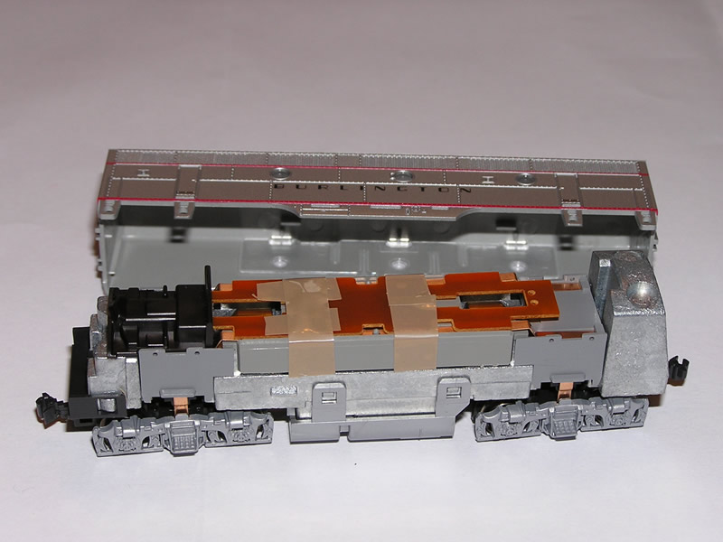 |
| Pict. 1: The frame and the body of the F3 B |
To remove the frame you can use some hard paper or thin plastic sheet that you insert to each side of the frame, then pull it gently. Once the frame is removed you discover the electronic board that would be replaced by a DN163K0B where you would have to remove the LED.
Rem: The tape holding the board is because I lost the small plastic clip! In any case this clip won't be used anymore.
The next step will be to remove the board and the pilot detail.
2.2 - Remove the board and pilot detail
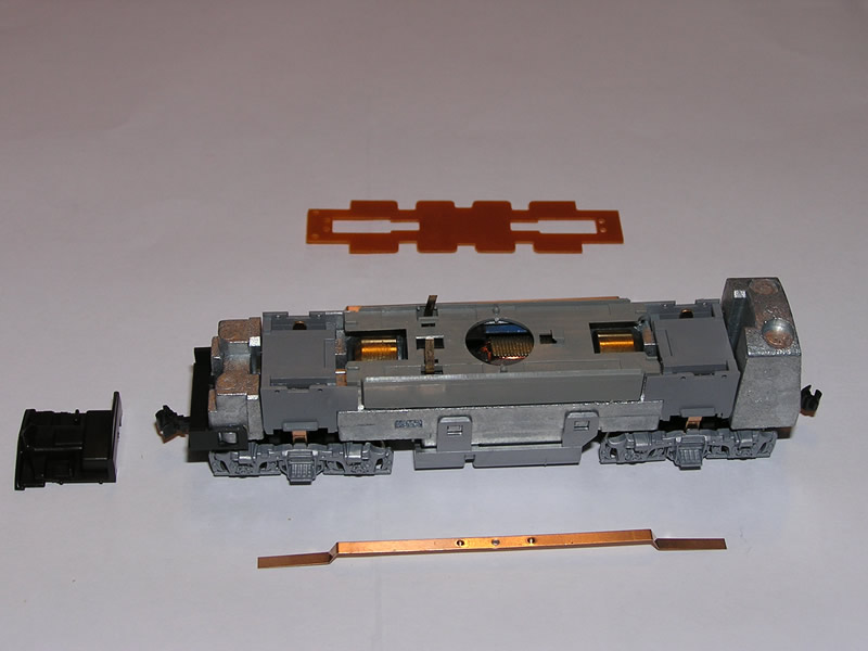 |
| Pict. 2:
The body of the F3 B with the electronic board and the coper rods removed. |
This is a very simple step. With a long-nosed plier remove the plastic clip that covers the motor pins. As it might jump when you remove it, be very careful! Then remove the pilot detail (the black piece in front) using a small screw driver.
Once this is done the last step is to gently remove the two power supply coper rod. You should get the different pieces in your hand like on the picture.
2.2 - Place the decoder
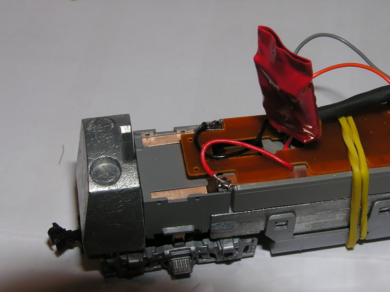 |
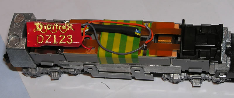
| Pict. 3: The black and the red wires are soldered on the coper rods. |
The next important step is to insulate the coper rods where they were having contact with the motor pins, it is to say where the plastic clip is positioned to hold the board. Use a small piece of electric tape that you wrap around the coper rod.
Cut the wires of the decoder, aproximatively 1.5", you can always adjust later before soldering. You won't need the following wires: yellow, white and blue. You can wrap those wires with some electric tape or use as I do some thermal tube.
The decoder
will be positioned at the back of the locomotive body on top of the board.
Place the two coper rods back in place and the board on top of them as
it was before. You can pass the black and red wire under the board and
let it go out by the sides of the board. Use a rubber band to hold the
board. Check that there is no contact between each motor pin and its matching
coper rod.
Once this is done, put some solder on each coper rod at the back of the locomotive. The black wire must be soldered to the left coper rod corresponding to the left rail. The red wire must be soldered to the right coper rod corresponding to the right rail.
2.3 - Finish the wiring
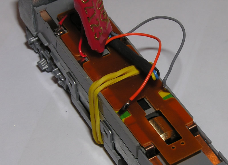 |
| Pict. 4: Soldering the motor wires |
The next step consists in soldering the decoder to the motor pins. This is a delicate step that must be done carefully because this part of the engine is quite sensitive to heat.
First you must put some solder on the pins. Just put a little of it and do it very quick to avoid over heating the brush cabinet. Once this is done solder the gray wire to the pin on the left side of the locomotive. You must be very fast, just put the wire in contact with the pin and solder it. The orange wire must be soldered the same way to the right pin of the motor.
2.5 - End of the operation
 |
| Pict. 5: The body is ready to receive the frame |
The last last step before puting back the frame is to place a piece of electric tape that will hold the board in position. If you put the rubber band as I did, you will have t cut it before you place the tape. Be carefull to place the tape so it cannot be seen through the small glasses on the sides of the frame.
Once this is done you just have to clip back the frame on the body.
Your F3 B is now ready for operation. You can see as well how to install a DN163K0b decoder in a F3 A unit. If you don't like soldering, you can also install this type of decoder in a F3 B unit removing the front LED.
Normally you should be using those locomotives to tract the Zephyr train, so you can see how I installed a TF4 decoder to control the lights of the Silver Sky car.